Today I got some time to create a short time lapse and game-play video from the very beginning to the current state of my “DYI Raspberry Pi powered pinball machine build from a princess bed”. Enjoy 🙂
Pinball
Raspberry Pi powered pinball machine – Gameplay impressions
Having a playable but only half-done pinball machine means still that there will be somebody who wants to play. Good thing is that I get a lot of feedback. Bad thing is development speed slows down quite a bit. Here are some impressions from my beta testers playing my DIY Raspberry Pi powered pinball machine:

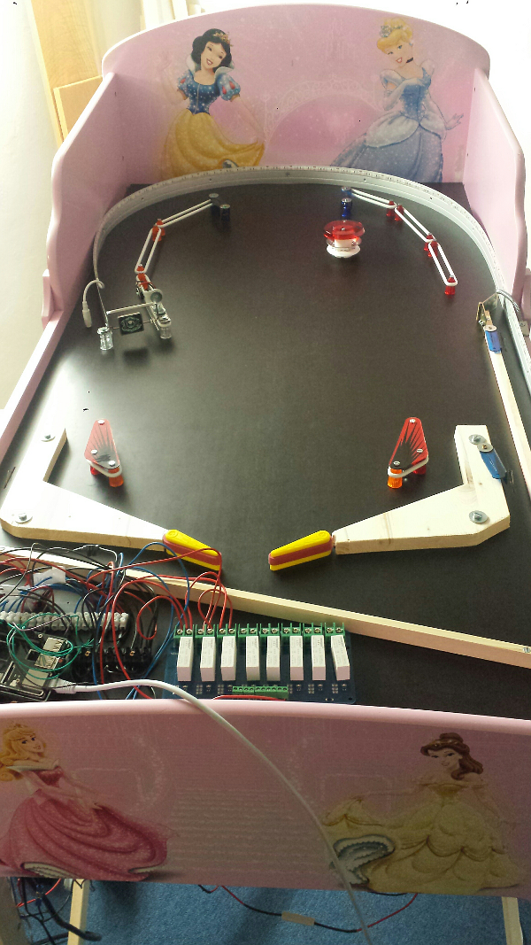
Highlight of the current state is the display. The display shows points for the current ball, total points, played ball and the high score since the game started. On top the display shows some comic speech bubbles whenever an event is triggered. The display is in fact an old 17″ monitor attached by some plates from the do-it-yourself store. According to my intelligence boys want to break the high score and girls want to break boys so there is always competition and fun. Best impression so far was two girls dressed up as princesses are playing with the pinball machine made from a princess bed. Gorgeous.
Technically some timeouts were adjusted and I introduced real multiprocessing for sound effects and background music. One “slingshot” is equipped with a switch to get points when the ball hits the rubber. So far so good. Whenever I have some spare time the second sling shot receives a switch as well and I want to add targets to the play field. Targets are great for incentives and should impact the game play as it becomes more interesting. Furthermore, I’ll play around with some barriers as the out lanes are hit too often at the moment.
Whenever the Raspberry Pi is switched on the operating system boots up and the program gets started at boot time. No X Window system is used which means I’m using a direct framebuffer as you can see in the source code. Starting a Python script at boot time is relatively easy as the following line can be used in a start/stop script:
start-stop-daemon --start --background --pidfile $PIDFILE --make-pidfile --exec $DAEMON --startas $DAEMON
Raspberry Pi powered pinball machine – Weak flipper finger
Today I spend some time investigating the issue with the weak flipper finger. First I debugged the software. Each 1000 loops the average time that the software needs in the loop was calculated. As the numbers are pretty stable around 0.005, which is the defined sleep timeout, we can say that the software runs inside our defined parameters and is quite reliably. Next the value of the HIGH flipper finger timeouts were increased by 0.01 to make sure that the magnetic field does not collapse to early. Without any effect. Last I inspected the flipper finger mechanics carefully and I notices that the right flipper finger requires a grain more power when the EOS switch was reached in comparison to the left flipper finger. In addition the EOS switch was triggered in the middle of the movement and not in the end phase. Long story short: The solution was to bend the EOS switch manually a bit to make sure that the switch is triggered at the end of the movement and the ball now gets kicked hard. Small details can have great impacts when building a DIY pinball machine 🙂
A short video that shows the current state:
Raspberry Pi powered pinball machine – The bumper
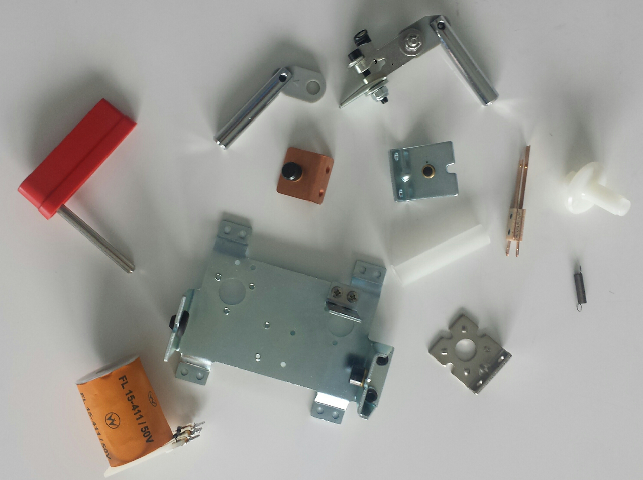
Yeah, bumper time. To be precise: pop bumper time. Here are the parts we have to assemble.
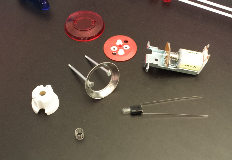
Worth to mention that the coil in the picture is an AC coil without diode and I soldered the diode myself to make it work in my DC voltage environment. And this is how it should work: a pop bumper kicks the ball when a ball hits the bumper plastic skirt. The plastic skirt triggers the switch which gives the impulse to fire up the coil. The coil pulls down the rod and ring assembly to accelerate the ball. Easy as eating cake. I started with mounting the coil:
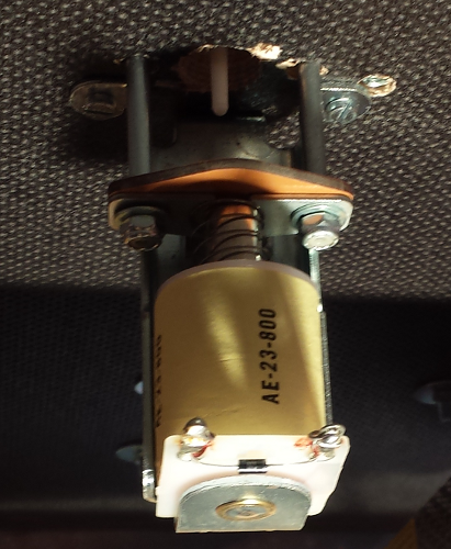
I used the bumper base for marking all holes and mounted the coil first with only one screw to make sure that all movable parts have enough space. Mounting pop bumper requires lots of drilling BTW. In the next step we place the skirt and fix the rod and ring assembly.
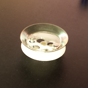
Screwing the bumper body and fixing all parts comes next. It is a bit tricky to stick the lamp pins through the tiny holes but who cares.

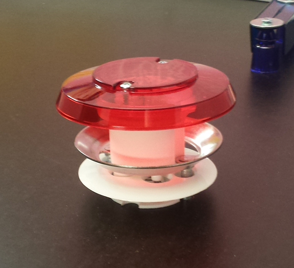
To make it look like a real bumper the last visible step is to add the cap.
The real tricky part is to make the bumper work in the way that the skirt does not get caught but activates the switch. In my case I replaced the original switch bracket with a piece of wood strip. I had to try several wood strips in different thickness to make it work. Try and error is the motto. Because I’m using a Raspberry Pi for the switch input testing was easy. I made sure that the bumper switch worked correctly before I wired the coils and relays. I also developed the logic and dry tested some “hiccups” to avoid burning the coil in advance by adding some special cool downs. Will play around and maybe adjust some timers though. And finally here is a current picture of the play field:
My pinball source code incl. all bumper specifics is available on Github as always, if you are interested. What I recognized while playing the current state is that I get sometimes a short but noticeable delay which results in weak flipper finger strength. As I’m using a Raspberry Pi 2 with multiple cores I introduces multiprocessor support for the sound module. Did not help as much as I thought so this issue is definitively something I need to address as the fun part depends a lot on precision. One solution to address this delays could be to introduce tmpfs and put all sounds into memory to avoid I/O wait conditions. So there is enough stuff on my to-do list. Get excited and have fun.
Raspberry Pi powered pinball machine – The spinner
Building your own pinball machine is not only huge fun. For me it’s learning and experimenting. One can become extremely creative. A good example was today’s “building a spinner mounting support”. The spinner is an original part of a real pinball machine. I got it second hand from a pinball shop. My mission today was to mount it above the lane, add a micro switch and develop the logic around light, sound and scoring. With just a couple of brackets, a metal rail, screws, nuts, washers and a standard micro switch I’m really proud of the result:

And best of all: it works. Which is quite cool as the whole project becomes really complex as everyone can see by just looking at the current state of my wiring:
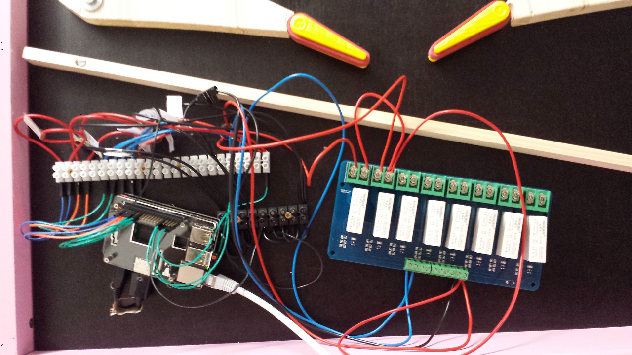
It looks really confusing and this is only the tip of the iceberg. But I have a fool-proof system that works for me. First of all I’ using a text file with all GPIO pin configurations. Next: all GPIO outgoing cables are tied to a well defined luster terminal input which is also documented. The text file also describes details which relay must be used. And most of the time I also label the wires. Most of the time means I tend to not label the wires until I lose the track 🙂
Raspberry Pi powered pinball machine – lights and sound
Adding light and sound effects is a huge difference when building a pinball machine. Even if I have currently only 3 triggers and two lights its quite fun to play around with the current state. I added a small effect class to the project to play any sounds one after another and to define simple light effects. This means blinking all around and because of a small random routine there is always some blink-blink action. Yeah, major improvement in terms of atmosphere.
The right flipper finger is not as strong as the left one and I’ve no idea why. Same resistors, resistance and pieces all around but noticeably weaker. Maybe something mechanically, will go ahead and ignore it for now. The next step is to define the places for more elements and the visual interface.
The source code is available if you are interested. I really enjoy Python as it makes stuff so much easier. I should add a video as just text or static images can’t express how cool this is. Stay tuned ’till the next milestone and have fun.
Building a Raspberry Pi powered pinball machine
Beginning of the year we replaced the bed of my daughter. First we wanted to give it away but nobody picked it up. In the same time I wanted to start a Raspberry Pi 2 project. One aim was to use the GPIO capabilities. After having the bed standing around several weeks the idea grow to build my own pinball machine where all logic is done by the Raspberry Pi 2. I don’t think that such a project would be possible several years ago but today you get the parts and pieces together without leaving the house. Great times,right. Here is a picture of the foundation:

With your power of imagination you see a pinball machine within this bed. No? Ok, let’s fast forward some days and have another look.

Yeah, there it is. A rough draft. You can see the already mounted shooter assembly and the shooter alley. The slingshot and the flipper finger placement was defined in this stage mostly intuitive. The board is a “multiplex board” or in German: “Siebdruckplatte”. The most important attribute of these boards for this project is that they don’t bend. My board is 230mm thick if you are curious. At this time I read a lot about flipper coils, power supplies and pinball machines in general as this field was completely new for me. One of the most confusion topics was the wiring of the flipper coils and more specific: the EOS switch. You can find many information around a normally closed (NC) EOS switch or a normal open (NO) one. As I’m tend to test stuff out I ordered all pieces of a flipper assembly and started to play around with it. Here are the pieces for my testing. Test bed becomes a complete new meaning in this project.
As you see, the EOS switch I got is an normally open (NO) one. After more research the picture was clear. Around the early ’90 was a technology switch from NC to NO EOS switches. The good news for me was that the technology switch was because control boards were introduced. As I want the logic within the Raspberry Pi this was exactly the stuff I needed. This means the EOS switch is connected to a GPIO input pin and the logic triggers a GPIO out pin which switches a relay to control the flipper coils. So we have already three different circuits and voltages. GPIO runs on 3,3 volt, the relay needs 5 volt and the flipper coil need high voltage. High voltage in my case means 36 volts and up to 5 amps. Some words to the flipper coils: A flipper coil has two different turns which have a different purpose. The first coil (HIGH) has just a few turns and almost no resistance. This coil kicks the flipper finger and the ball hard. The other coil (HOLD) has far more turns and a higher resistance. Purpose is to hold the flipper finger up when the flipper button is pressed a longer period of time. The issue with the HIGH coil is that it is nearly a short-circuit and draws a huge amount of current. I burned a relay in the process because my relays can only handle 5 amps and I started with 0.5 seconds HIGH. At the moment the HIGH coil is only energized 0.04 seconds and works just great. This said playing with flipper coils is serious business and we need resistors for protection ;). Here a picture of my first wiring prototype and processing the input with the Raspberry Pi:
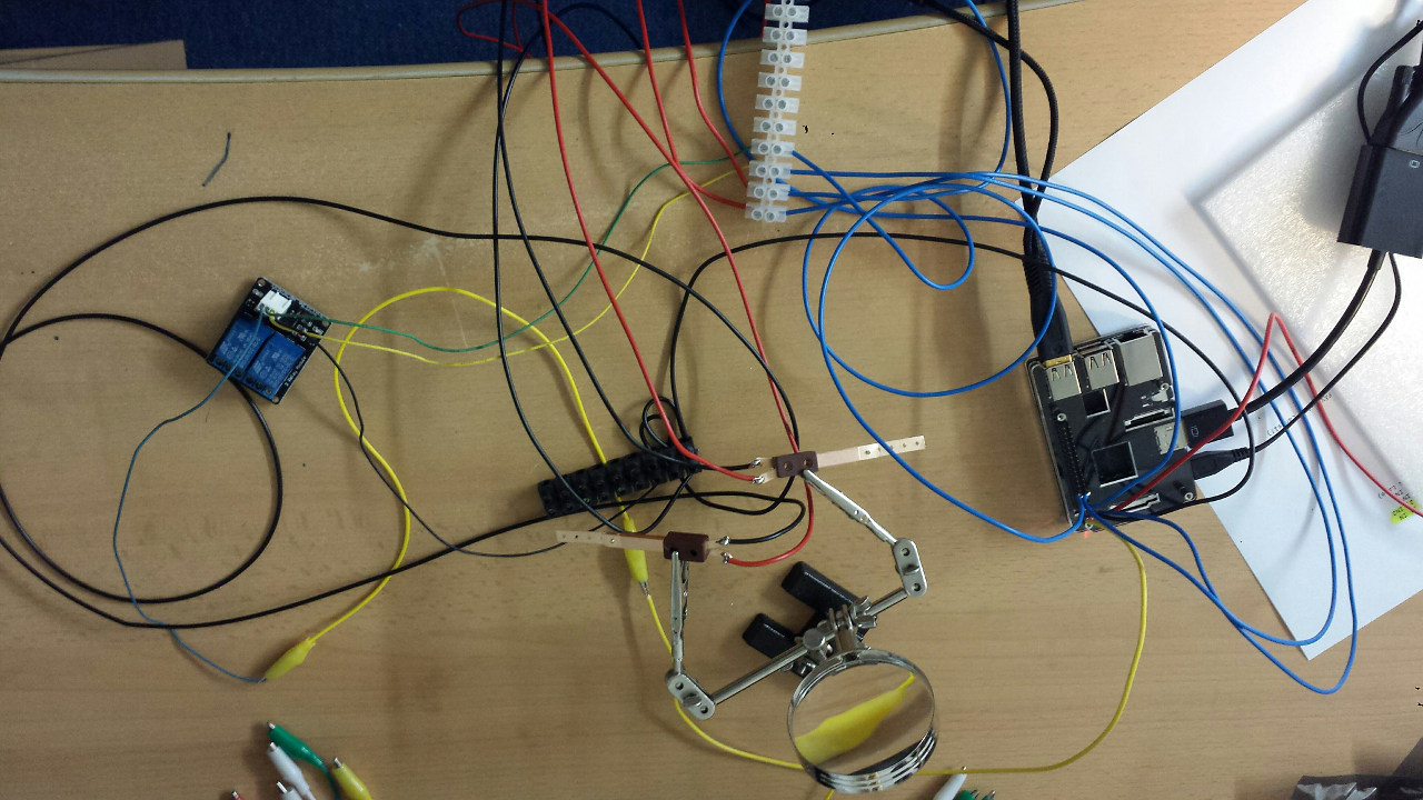
Today was a good day as I finished the basic flipper logic, have a quite amount of wiring done and can control two different lights with the Raspberry Pi. Neat!

Now comes the part to place more components like bumpers and targets and to develop the first counter/light logic. Whenever I hit the next milestone I will post again. The code will be published on GitHub within the next days. Have fun!