Beginning of the year we replaced the bed of my daughter. First we wanted to give it away but nobody picked it up. In the same time I wanted to start a Raspberry Pi 2 project. One aim was to use the GPIO capabilities. After having the bed standing around several weeks the idea grow to build my own pinball machine where all logic is done by the Raspberry Pi 2. I don’t think that such a project would be possible several years ago but today you get the parts and pieces together without leaving the house. Great times,right. Here is a picture of the foundation:

With your power of imagination you see a pinball machine within this bed. No? Ok, let’s fast forward some days and have another look.

Yeah, there it is. A rough draft. You can see the already mounted shooter assembly and the shooter alley. The slingshot and the flipper finger placement was defined in this stage mostly intuitive. The board is a „multiplex board“ or in German: „Siebdruckplatte“. The most important attribute of these boards for this project is that they don’t bend. My board is 230mm thick if you are curious. At this time I read a lot about flipper coils, power supplies and pinball machines in general as this field was completely new for me. One of the most confusion topics was the wiring of the flipper coils and more specific: the EOS switch. You can find many information around a normally closed (NC) EOS switch or a normal open (NO) one. As I’m tend to test stuff out I ordered all pieces of a flipper assembly and started to play around with it. Here are the pieces for my testing. Test bed becomes a complete new meaning in this project.
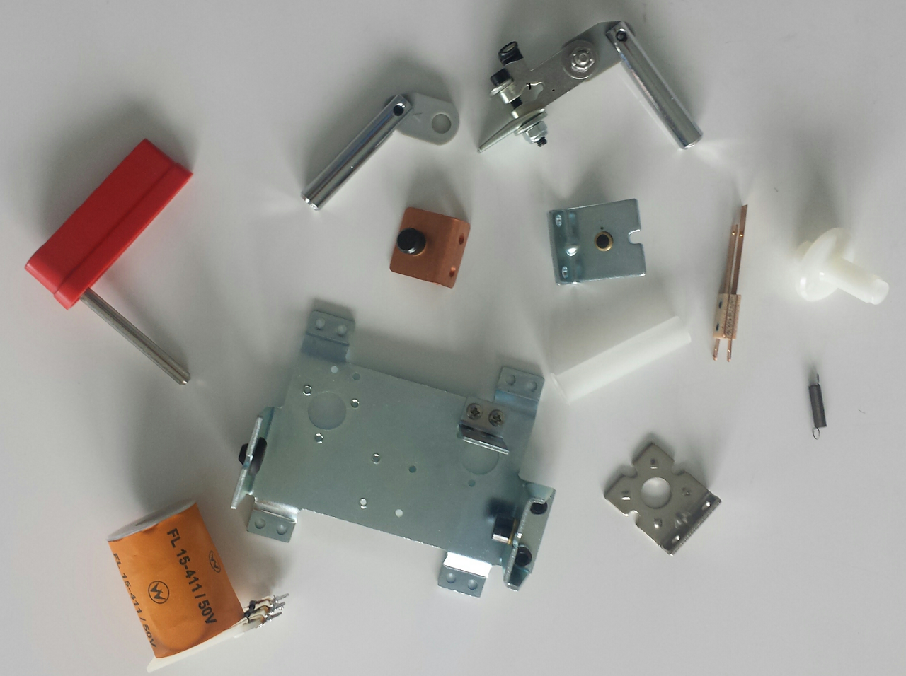
As you see, the EOS switch I got is an normally open (NO) one. After more research the picture was clear. Around the early ’90 was a technology switch from NC to NO EOS switches. The good news for me was that the technology switch was because control boards were introduced. As I want the logic within the Raspberry Pi this was exactly the stuff I needed. This means the EOS switch is connected to a GPIO input pin and the logic triggers a GPIO out pin which switches a relay to control the flipper coils. So we have already three different circuits and voltages. GPIO runs on 3,3 volt, the relay needs 5 volt and the flipper coil need high voltage. High voltage in my case means 36 volts and up to 5 amps. Some words to the flipper coils: A flipper coil has two different turns which have a different purpose. The first coil (HIGH) has just a few turns and almost no resistance. This coil kicks the flipper finger and the ball hard. The other coil (HOLD) has far more turns and a higher resistance. Purpose is to hold the flipper finger up when the flipper button is pressed a longer period of time. The issue with the HIGH coil is that it is nearly a short-circuit and draws a huge amount of current. I burned a relay in the process because my relays can only handle 5 amps and I started with 0.5 seconds HIGH. At the moment the HIGH coil is only energized 0.04 seconds and works just great. This said playing with flipper coils is serious business and we need resistors for protection ;). Here a picture of my first wiring prototype and processing the input with the Raspberry Pi:
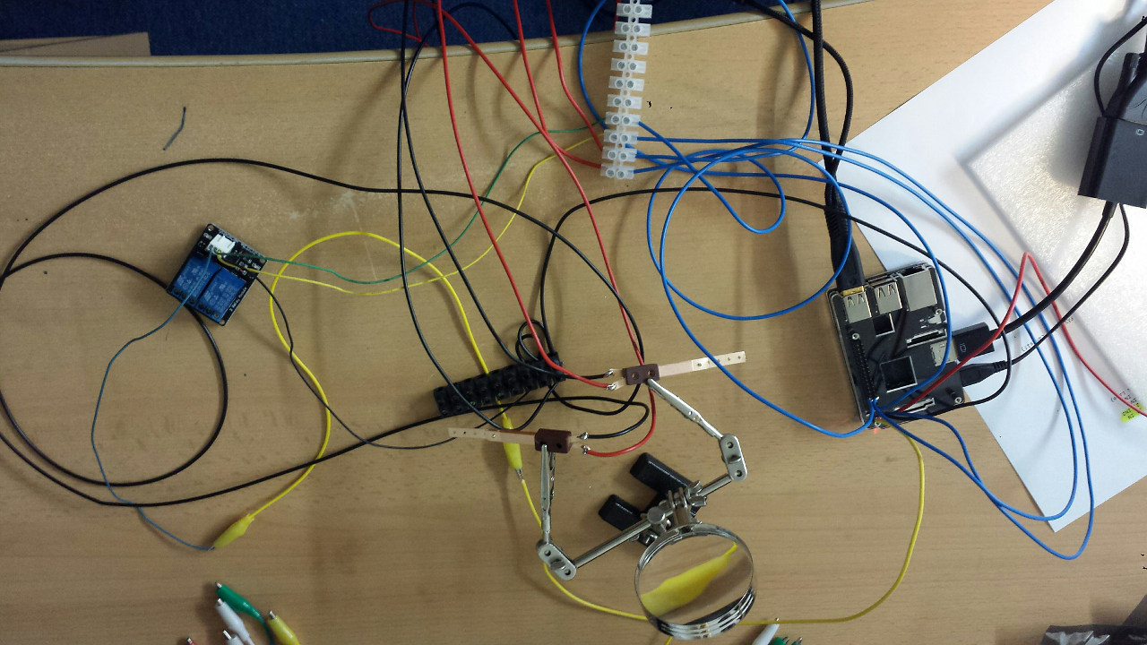
Today was a good day as I finished the basic flipper logic, have a quite amount of wiring done and can control two different lights with the Raspberry Pi. Neat!

Now comes the part to place more components like bumpers and targets and to develop the first counter/light logic. Whenever I hit the next milestone I will post again. The code will be published on GitHub within the next days. Have fun!